Gathering Data v1 Part 2
In this post, we will cover:
- a way to get an object’s bounding box
- a way to get the extreme coordinates of the bounding box
- a way to take a screenshot
- a way to tag the locations gathered, to the screenshot taken
Getting an object’s bounding box
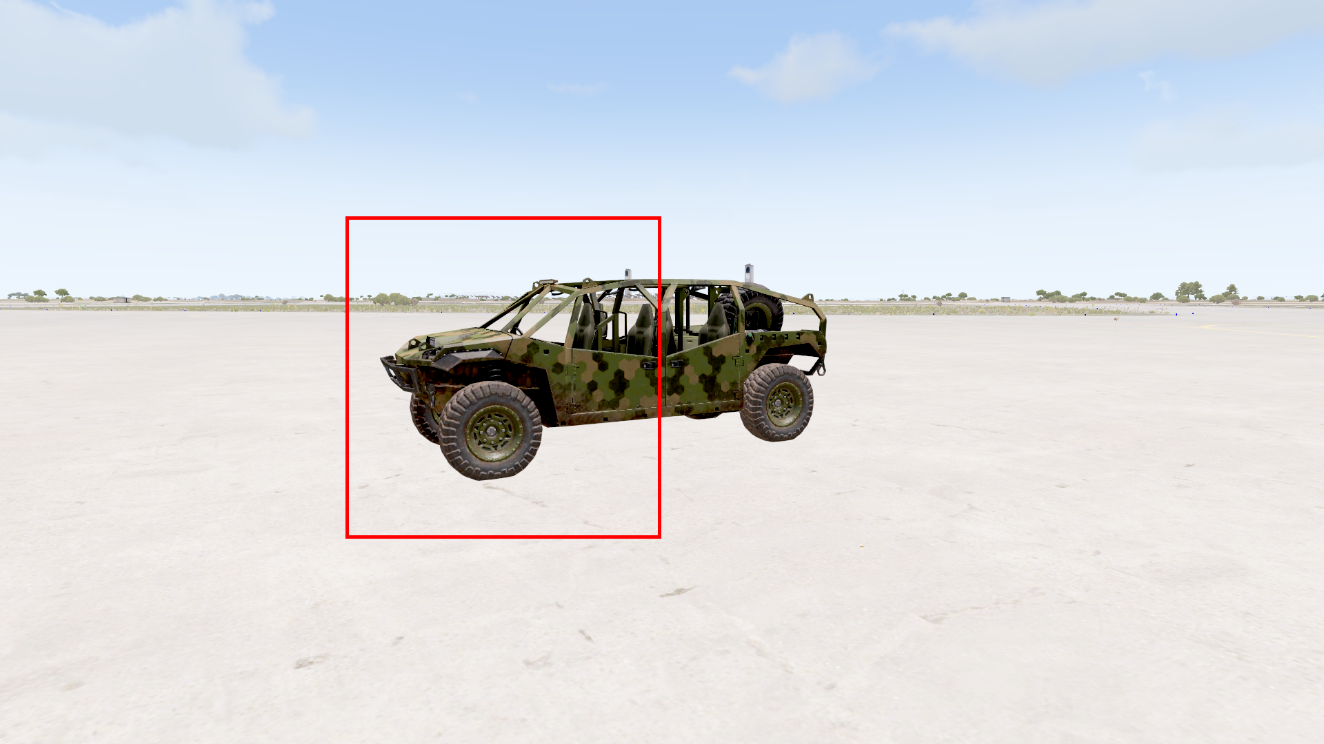
We can make use of the function boundingBoxReal, where it returns an array of [[xmin, ymin, zmin], [xmax, ymax, zmax], boundingSphereRadius]. As the coordinates for [xmin, ymin, zmin], [xmax, ymax, zmax] are relative to the object’s own position, it is slightly more difficult to implement. As such, a simple method of getting the bounding box, would be to use the object position and add boundingSphereRadius to all directions. The code below draws the bounding box using the simple (but inaccurate) method.
THIS IS ONLY A VERY VERY VERY ROUGH ESTIMATE FOR THE BOUNDING BOX. As you can see in the image below, it is not accurate at all. This WILL affect training and accuracy of the model.
DrawBB = {
	params ["_obj", "_objpos"];
	_box = (2 boundingBoxReal _obj);

	private _min = [];
	private _max = [];

	for "_i" from 0 to 3 -1 do {
		_min pushBack ((_objpos select _i) - ((_box select 2)/4));
		_max pushBack ((_objpos select _i) + ((_box select 2)/4));
	};

	_corners = [
		_min,
		[_max select 0, _min select 1, _min select 2],
		[_min select 0, _max select 1, _min select 2],
		[_max select 0, _max select 1, _min select 2],
		[_min select 0, _min select 1, _max select 2],
		[_max select 0, _min select 1, _max select 2],
		[_min select 0, _max select 1, _max select 2],
		_max
	];

	// Define edges (pairs of corner indices)
	_edges = [
		[0, 1], [1, 3], [3, 2], [2, 0],
		[4, 5], [5, 7], [7, 6], [6, 4],
		[0, 4], [1, 5], [2, 6], [3, 7]
	];

	// Draw edges
	{
		_start = _corners select (_x select 0);
		_end = _corners select (_x select 1);
		drawLine3D [_start, _end, [1, 0, 0, BBLineWidth_GlobalVariable]]; // Red lines
	} forEach _edges;
};
Code explanation
_box = (2 boundingBoxReal _obj);

private _min = [];
private _max = [];

for "_i" from 0 to 3 -1 do {
	_min pushBack ((_objpos select _i) - ((_box select 2)/4));
	_max pushBack ((_objpos select _i) + ((_box select 2)/4));
};
Basically, this iterates thru the returned array, and stores the xyz min and max values.
We then create the corners of the bounding box using the following code. Basically, it iterates through the combinations of min and max xyz values.
_corners = [
	_min,
	[_max select 0, _min select 1, _min select 2],
	[_min select 0, _max select 1, _min select 2],
	[_max select 0, _max select 1, _min select 2],
	[_min select 0, _min select 1, _max select 2],
	[_max select 0, _min select 1, _max select 2],
	[_min select 0, _max select 1, _max select 2],
	_max
];
Then, we define the edges of the bounding box (this is to draw lines to view the boxes in-game). Basically, this links each of the corner to another corner.
_edges = [
	[0, 1], [1, 3], [3, 2], [2, 0],
	[4, 5], [5, 7], [7, 6], [6, 4],
	[0, 4], [1, 5], [2, 6], [3, 7]
];
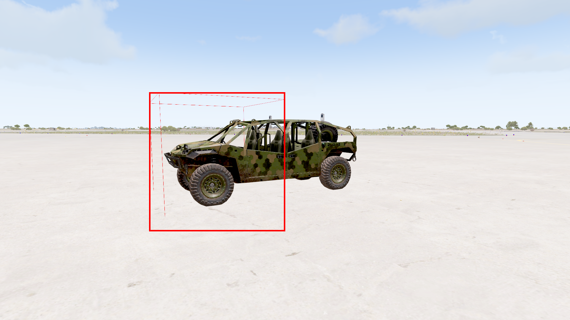
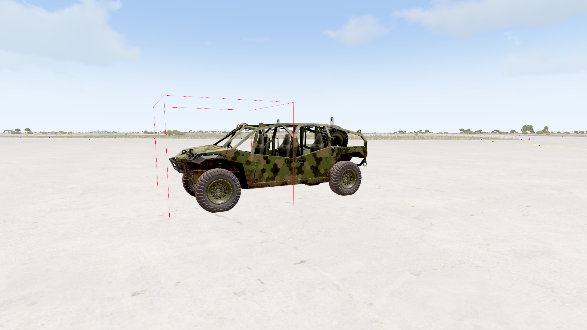
Finally, using the edges, we can draw the bounding box on in-game.
{
	_start = _corners select (_x select 0);
	_end = _corners select (_x select 1);
	drawLine3D [_start, _end, [1, 0, 0, BBLineWidth_GlobalVariable]]; // Red lines
} forEach _edges;
Getting extreme coordinates of bounding box
In order to create a bounding box for the screenshots, we need to get the extreme on-screen xy coordinates of the bounding box of the object.
To do this, we have made a function GetLargestAndSmallestXYOnScreen.
// returns xmin, ymin, xmax, ymax array if obj is on screen, else returns false
GetLargestAndSmallestXYOnScreen = {
	params ["_obj", "_objpos", "_objname"];

	private _output = false;
	// Only continue if it is on screen
	if (_obj call CheckOnScreen) then {
		_box = (2 boundingBoxReal _obj);

		private _min = [];
		private _max = [];

		for "_i" from 0 to 3 -1 do {
			_min pushBack ((_objpos select _i) - ((_box select 2)/4));
			_max pushBack ((_objpos select _i) + ((_box select 2)/4));
		};

		// 3d in-game coords
		_corners = [
			_min,
			[_max select 0, _min select 1, _min select 2],
			[_min select 0, _max select 1, _min select 2],
			[_max select 0, _max select 1, _min select 2],
			[_min select 0, _min select 1, _max select 2],
			[_max select 0, _min select 1, _max select 2],
			[_min select 0, _max select 1, _max select 2],
			_max
		];

		private _minX = 10;
		private _minY = 10;
		private _maxX = -10;
		private _maxY = -10;

		// convert each in-game corner to screen coords
		{
			private _retcoords = worldToScreen (_x);

			// check if _retcoords is on screen first
			if (((safeZoneX < (_retcoords select 0)) &&
			((_retcoords select 0) < safeZoneW)) &&
			((safeZoneY < (_retcoords select 1)) &&
			((_retcoords select 1) < safeZoneH)))
			then{
				// since it is on screen, we can then try to find the min and max
				// check if x is min
				_minX = if ((_retcoords select 0) < _minX) then {
					(_retcoords select 0)
				} else {
					_minX
				};
				// check if x is max
				_maxX = if ((_retcoords select 0) > _maxX) then {
					(_retcoords select 0)
				} else {
					_maxX
				};
				// check if y is min
				_minY = if ((_retcoords select 1) < _minY) then {
					(_retcoords select 1)
				} else {
					_minY
				};
				// check if y is max
				_maxY = if ((_retcoords select 1) > _maxY) then {
					(_retcoords select 1)
				} else {
					_maxY
				};
			} else {
				false;
			}
		} forEach _corners;

		// check if minX maxX minY maxY is still orginal value
		// if they are still original value, means the object is out of frame
		if ((_minX != 10) &&
		(_maxX != -10) &&
		(_minY != 10) &&
		(_maxY != -10)) then {
			// convert minX maxX minY maxY to absolute screen coords.
			private _convertedxmin = (1920 / (abs safeZoneW)) * (_minX + abs safeZoneX);
			private _convertedxmax = (1920 / (abs safeZoneW)) * (_maxX + abs safeZoneX);
			private _convertedymin = (1080 / (abs safeZoneH)) * (_minY + abs safeZoneY);
			private _convertedymax = (1080 / (abs safeZoneH)) * (_maxY + abs safeZoneY);
			_output = [_convertedxmin, _convertedymin, _convertedxmax, _convertedymax];
			_output;
		} else {
			systemChat "Bounding Box OUT OF FRAME!";
			_output;
		};
	} else {
		_output;
	};
	_output;
};
Code explanation
Similar to the previous section, it first gets the corners of the object’s bounding box.
_box = (2 boundingBoxReal _obj);

private _min = [];
private _max = [];

for "_i" from 0 to 3 -1 do {
	_min pushBack ((_objpos select _i) - ((_box select 2)/4));
	_max pushBack ((_objpos select _i) + ((_box select 2)/4));
};

// 3d in-game coords
_corners = [
	_min,
	[_max select 0, _min select 1, _min select 2],
	[_min select 0, _max select 1, _min select 2],
	[_max select 0, _max select 1, _min select 2],
	[_min select 0, _min select 1, _max select 2],
	[_max select 0, _min select 1, _max select 2],
	[_min select 0, _max select 1, _max select 2],
	_max
];
After which, we iterate through each corner, convert it to screen coords, and keep track of the maximum and minimum x and y values.
// convert each in-game corner to screen coords
{
	private _retcoords = worldToScreen (_x);

	// check if _retcoords is on screen first
	if (((safeZoneX < (_retcoords select 0)) &&
	((_retcoords select 0) < safeZoneW)) &&
	((safeZoneY < (_retcoords select 1)) &&
	((_retcoords select 1) < safeZoneH)))
	then{
		// since it is on screen, we can then try to find the min and max
		// check if x is min
		_minX = if ((_retcoords select 0) < _minX) then {
			(_retcoords select 0)
		} else {
			_minX
		};
		// check if x is max
		_maxX = if ((_retcoords select 0) > _maxX) then {
			(_retcoords select 0)
		} else {
			_maxX
		};
		// check if y is min
		_minY = if ((_retcoords select 1) < _minY) then {
			(_retcoords select 1)
		} else {
			_minY
		};
		// check if y is max
		_maxY = if ((_retcoords select 1) > _maxY) then {
			(_retcoords select 1)
		} else {
			_maxY
		};
	} else {
		false;
	}
} forEach _corners;
Screenshot
To take a screenshot of the current scene, we can call screenshot. This saves it to the profile’s screenshot folder. It is important to note that there is a default folder size limit of 250MB, which can be changed by adding maxScreenShotFolderSizeMB = 2000; // 2 GB to the end of the profile file.
Tagging logs to screenshots
Screenshots can have a custom name. As such, we use the timestamp to tag each log to the screenshot. At the time of capture, the timestamp is generated. This is used to name the screenshot image, as well as to tag each log.
We can output each log to a logfile by using the command diag_log.
For example, we can generate a timestamp by using:
private _currentTime = systemTime apply {if (_x < 10) then {"0" + str _x} else {str _x}};
private _currentTimeStr = "";
_currentTime apply {_currentTimeStr = _currentTimeStr + _x};
For the screenshot, we save it with a custom name:
private _saveSSName = _currentTimeStr + ".png";
screenshot _saveSSName;
And for the log, we have:
diag_log str(str(_x select 1) + "|" + str (_convertedxmin) + "|" + str (_convertedymin) + "|" + str (_convertedxmax) + "|" + str (_convertedymax) + "|" + str (_currentTimeStr));
Thus, when we are processing the data, we can match each image to the respective log.
The log file will contain chunks like this:
20:25:18 """---START-CV-DATA-FRAME---"""
20:25:18 """""""O_G_Offroad_01_armed_F""""|891.191|558.857|1317.49|894.316|""""20250625202518480"""""""
20:25:18 """""""O_G_Offroad_01_AT_F""""|682.094|32.8631|928.484|254.214|""""20250625202518480"""""""
20:25:18 """""""I_MRAP_03_gmg_F""""|1963.72|60.5509|2190.05|149.924|""""20250625202518480"""""""
20:25:18 """""""Land_Flush_Light_green_F""""|1413.64|13.6794|1430.97|21.4241|""""20250625202518480"""""""
20:25:18 """""""Land_Flush_Light_green_F""""|1747.42|201.867|1765.87|210.75|""""20250625202518480"""""""
20:25:18 """""""Land_Flush_Light_green_F""""|2186.72|451.54|2206.57|462.046|""""20250625202518480"""""""
20:25:18 """""""Land_Flush_Light_green_F""""|1277.01|941.161|1302.12|955.228|""""20250625202518480"""""""
20:25:18 """""""Land_Flush_Light_green_F""""|2163.18|781.835|2185.62|794.689|""""20250625202518480"""""""
20:25:18 """""""Land_Flush_Light_green_F""""|430.441|1091.79|458.455|1107.05|""""20250625202518480"""""""
20:25:19 """---END-CV-DATA-FRAME---"""
This can then be run through a python program to output a txt file that conforms to the YOLO format of class x_center y_center width height, with x_center y_center width height being normalized.
End result of the bounding box drawn will look something like this.